Commercial Chimney Systems
The aim of this section is to provide a clearer understanding of how chimneys and flues should be selected and installed in commercial applications.

January 2021 saw the introduction of the UK CA mark (UK Conformity Assessed) which replaces the CE mark in Great Britain. (The CE mark will still be required in Northern Ireland and for products being sold into the European Union). The CE mark will no longer be valid in Great Britain from 1st January 2023. BS EN standards will become BS standards.
Diagrams are for illustrative purposes only and at all times boiler and flue manufacturers’ instructions should be followed.
The terms flue and chimney are often used interchangeably. The flue is the working part of the chimney, conveying the products of combustion safely to the atmosphere. The chimney includes the shaft within which the flue is housed.
A chimney or flue can be constructed from a variety of materials. The choice includes clay, pumice/concrete and plastic but the most commonly used material is stainless steel. For that reason, this guide will focus on stainless steel flues. The type of flue selected depends on the application and on the fuel used. The stainless steel UKCA/CE designation provides clear guidance as to the appliances the flue should be used on.
Historically flues have worked under negative pressure drawing the product of combustion from the appliance. Under negative pressure a successful “chimney draw” is dependent on the difference in air pressure between the appliance and the top of the chimney, (created by the height), and the difference in temperature between the appliance’s exhaust gas and the outside temperature. Many appliances now operate with positive pressure. Appliances can also be condensing or non-condensing. The UKCA/CE designation of the flue will guide you to the correct flue choice.
The route taken by the flue can have a significant impact on performance. The straighter and more vertical the chimney the better.
It is essential to choose a flue diameter that matches the output from the appliance. An adequate air supply is also required for the appliance to operate safely and efficiently.

A key document is the Construction Products Regulations Mandate 105 “Chimney, flues and specific products”. It covers the requirements for all chimneys and flues to be used in any type of building.
It stipulates that the chimney and flue should be considered as a “Part of the Building” and therefore must comply with the “The Construction Products Regulations”.
The EU Construction Products Regulation (No. 305/2011) (CPR) lays down the harmonised conditions for the sale and supply of construction products and is directly applicable in its entirety into UK law.
The Construction Products Regulations: came into force in the UK from 1st of July 2013. Designers, architects, builders and heating engineers should be aware and understand the requirements on construction products.
The Construction Products Regulations require that all chimney and flue products are UKCA/CE marked. The UKCA/CE mark designation defines the operational and performance limits.
The UKCA/CE mark classification should be used to select the correct flue for the chosen application.
Making Sense of UKCA/CE Designations
One of the key features of the European Standard for metal chimneys (EN 1856) is a user-readable classification system that designates the features of the product. A label showing the classification must go with each flue component. Understanding the classification can make the job of selecting the right flue much easier and will allow you to compare different flues. It’s easy to use so long as you know the keys.
The diagram below unlocks the coded information.
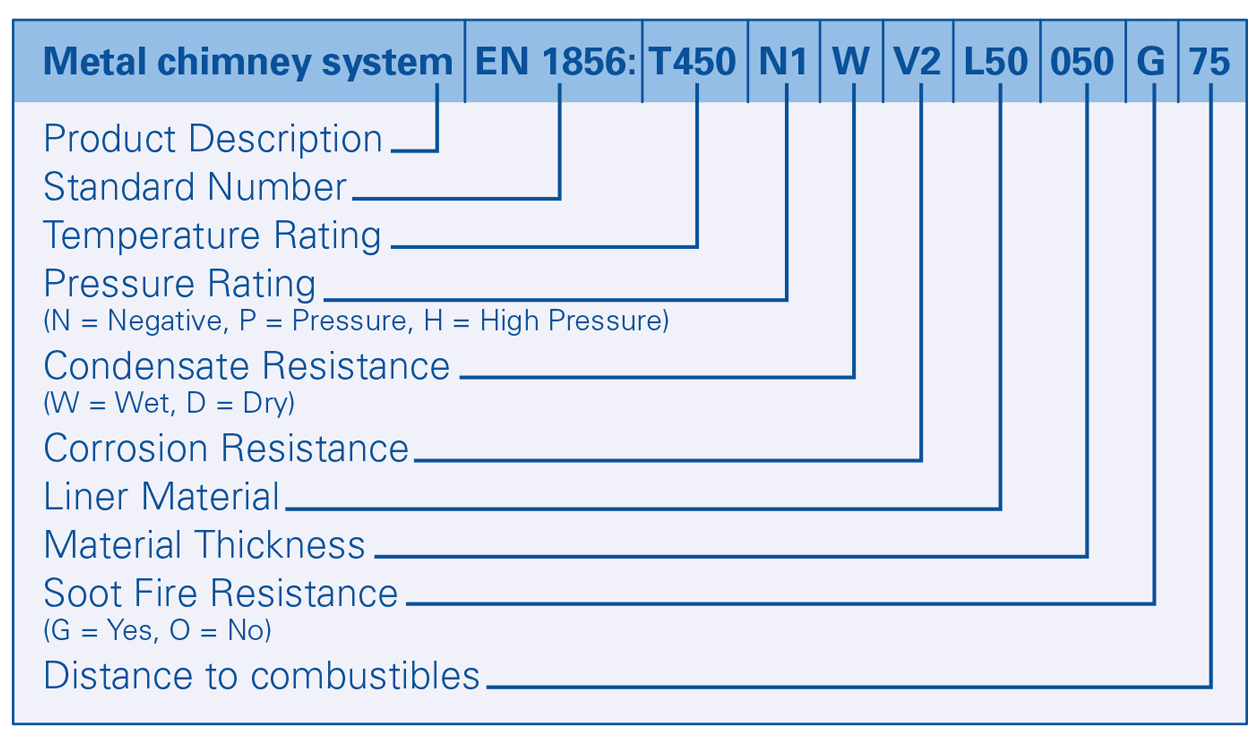
Picking out a few of the main points:
Temperature Rating Minimum temperature (°C) for continuous use of the flue. T400 is suitable for multi-fuel. T200 is suitable for gas and oil.
Pressure Rating Expressed as N for negative pressure applications, P for positive pressure and H for high positive pressure. Maximum allowed leakage rates are as defined below.
For most applications, N1 is suitable for conventional negative pressure boiler installations. P1 is required for most positive pressure and fan flued boilers. H is for high pressure applications e.g. diesel generators, when the leakage rate is normally subject to specifier requirement.
| Leakage rate (1/sec/m3) | Test pressure (Pa) | |
| N1 | 2.0 | 40 |
| P1 | 0.006 | 200 |
| P2 | 0.12 | 200 |
| H1 | 0.006 | 5000 |
| H2 | 0.12 | 5000 |
Condensate Resistance Suitability for wet or dry operation. W designates ability to contain condensate within the flue, i.e. operating in the wet and dry conditions created by condensing appliances. D designates ability to operate under dry conditions only, usually meaning a flue gas temperature high enough to avoid condensate formation. Designation D3, for example, indicates that the flue is resistant to the products of combustion from burning wood under dry conditions.
Corrosion Resistance This is fuel dependent as follows:
V1 Resistant to attack from products of combustion from gas.
V2 Resistant to attack from products of combustion from light oil (sulphur content up
to 0.2%) and natural wood. If the flue passes the V2 wet test then it is also deemed to comply with D3
under dry conditions.
V3 Resistant to attack from products of combustion from heavy oil (sulphur content >
0.2%), solid fuels and peat.
VM Not tested but rating declared by the manufacturer.
Linear Material Specification Two features are specified, firstly a code for the minimum material grade and secondly material thickness:
Normally liners expected to withstand the corrosion effect of multifuel, wood or heavy oil are made with
316L. Light oil is less corrosive and normally 304 has proved adequate in dry conditions, but in the
increasingly common wet conditions created by high efficiency boilers, a higher grade is required (316L).
L11 Aluminium 99% pure
L20 304
L30 304L
L40 316
L50 316L
Thickness e.g. 060 means 0.6mm
Soot Fire Resistance and Distance to Combustibles Expressed as either G, for soot fire resistance or O for not, followed by the declared minimum distance to combustibles expressed in mm. To obtain the G classification means that the product has been tested at 1000°C for 30 minutes and remains intact. The temperature of combustible material at the designated distance must not exceed 100°C at an ambient temperature of 20°C.
Distance to Combustibles for Connecting Flue Pipe tested to BS EN 1856-2 also have an additional classification M (Measured) or NM (Not Measured). If not measured the minimum distance to combustibles should be 3 times the internal diameter of the connecting flue pipe. Connecting flue pipes to BS EN 1856-1 should be used in accordance with the manufacturer’s declared distance to combustibles..
System Chimneys approved to EN1856-1, when used as a connecting flue pipe, should be used in accordance with the manufacturer’s declared distance to combustibles.
It is worth noting that the tests for biomass have been carried out on woody biomass only.
The installation of flues for domestic appliances under 70kW output in residential buildings is covered in Approved Document J (England and Wales), Building Regulations Technical Standards in Scotland and Part L in N. Ireland. There is no equivalent guidance for the installation of chimneys and flues with appliances rated higher than 70kW.

However, the following regulations cover the design and installation of chimneys and flues:
BSEN 13384-1:2015 Chimneys. Thermal and fluid dynamic calculation methods. Chimneys serving one heating appliance.
BSEN 13384-2:2015 Chimneys. Thermal and fluid dynamic calculation methods. Chimneys serving more than one heating appliance.
BSEN 1443: 2003 Chimneys – general requirements.
BSEN 1856 - 1: 2009 Chimneys. Requirements for metal chimneys. System chimney products.
BSEN 1856 - 2: 2009 Chimneys. Requirements for metal chimneys. Metal liners and connecting metal flue pipes.
BSEN 1457: 2012 Chimneys, Clay/Ceramic flue liners. Requirements and test methods.
BSEN 15287+A1: 2010 Chimneys - Design, installation and commissioning of chimneys.
Pt
1: Chimneys for non-room sealed heating appliances.
BSEN 15287-2:2008 Chimneys. Clay/ceramic flue liners. Flue liners operating under wet conditions. Requirements and test methods.
BSEN 1858:2008+A1:2011 Chimneys. Components. Concrete flue blocks.
BSEN 14471:2013+A1:2015 Chimneys. System chimneys with plastic flue liners. Requirements and test methods.

Stainless steel flues are categorised into different systems according to the application they are designed for.
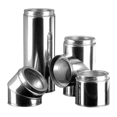
Twin Wall System Chimneys
High quality stainless steel system chimneys consisting of two concentric stainless steel metal walls with preinstalled insulation filling the annular space between them. The systems are available in different models for use with:
- Condensing and non-condensing multi fuel appliances.
- Diesel and gas fuel generators and CHP systems.
- Appliances operating under high positive pressure at low and high temperatures.
Can also be used as a connecting flue pipe.
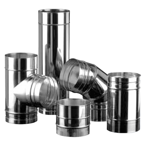
Single Wall
Designed for use on multi-fuel applications as a chimney liner or connecting flue pipe on condensing and noncondensing applications.
Flexible Liner
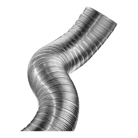
Stainless steel flexible liners can be used to reline an existing chimney. Care must be taken when selecting a flexible liner as there are two types of flexible liners:
- Single skin liners for use with gas appliances and
- Twin skin liners, manufactured from overlapping strips of high grade stainless steel to give a smooth sealed flue-way. These liners should be used with wood and multi-fuel appliances as well as condensing gas and oil appliances, where tested and approved for these applications.
The proposed flue should be designed in plans and tested using a flue test programme prior to installation. The test calculation will show if the flue route will facilitate the required draught to allow the flue gases to escape freely to the atmosphere.
The use of a fan may be required. The appropriate fan controller should also be specified at the design stage. (The flue must be capable of removing the flue gases if the power or fan fails). The boiler manufacturer’s instructions should always be followed.
The temperature and pressure rating of the appliance will drive the flue choice. The maximum and minimum output of modulating appliances should always be considered.
Bends in the Chimney
Where possible, bends in the flue should be avoided, as a straight vertical chimney performs better.
Where System Chimneys are used, always use the standard offset components which are available from the chimney manufacturer.
For natural draft appliances it is recommended that a vertical rise of 600mm should be allowed immediately above the appliance before any change of direction. It is important that there is easy access for cleaning, particularly at any change of direction in the flue. This can be achieved with the use of swept elbows that incorporate both debris collection and an inspection point.
Flue Sizing
Flue sizing, to establish the optimum flue height and diameter, should be carried out in accordance with BSEN 13384-1:2015 for single wall appliances and with BSEN 13384-2:2003+A1:2009 for more than one appliance. It is important to match the internal diameter of the flue with the outlet on the appliance. It should never be less than the outlet diameter of the appliance. The appliance manufacturer’s chimney sizing recommendations should always be followed.
Insulation is Key
One of the keys to a well performing chimney is consistent insulation along the complete length of the flue.
Horizontal Runs
Horizontal runs should not exceed the appliance manufacturer’s instructions.
Natural draught flues serving natural draught appliances should not pass downwards on their route to the terminal. Where appropriate the flue shall be inclined at not less than 2.5° back to the appliance.
The appliance manufacturer’s instructions should always be consulted.
Chimney & Flue Construction
The chimney and flue must be supported properly throughout its length. The flue manufacturer’s instructions should always be followed.
Joints must be located where they can be inspected and tested for integrity. There should also be adequate test points along the length of the flue to allow for smoke, combustion or leakage testing.
If a mast is required to support the flue specialist advice should be sought.
The UKCA/CE designation of the flue specifies the distance required between the flue and combustible material to allow the safe operation of the flue. This must be adhered to.
When a flue pipe enters a masonry chimney, ideally, the angle of the entry should be inclined upwards at least 45° and must not protrude into the chimney beyond its inner face. If this is not practicable, the entry of the flue pipe must not restrict the ability of the chimney to exhaust the combustion gases safely. Where necessary, a survey should be carried out prior to installation. The entry point must be at least 250mm from the base of the chimney and there must also be an inspection point at the base of the chimney and flue.
It is always recommended the flue should be sleeved as it passes through the wall.
Termination
It is essential that a chimney terminate in a position where the combustion products can disperse readily to the environment without causing a nuisance or danger to people or property.
A terminal is required on natural draught and fan assisted flues that have an internal diameter of less than 170mm. Terminals are not normally required for larger diameters as they may negate the requirement to achieve a good dispersion of flue gases.
Terminals must be clear of any obstructions and clear of any openings into a building, for example a window, door or air inlet.
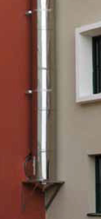
Wall terminations should be directed away from the building so that the flue gases can freely disperse.
The specification of the flue terminal will have been determined by the terminal manufacturer.
The flue terminal should be designed to have a minimum resistance to the flue gas flow, while providing protection from the ingress of rain, snow and small birds.
It should also minimise downdraught and be designed to encourage the discharge of combustion products under a wide range of wind conditions.
The total free area of outlet openings on the terminal must be appropriate for the appliance(s) used with that chimney or flue. As a guideline the free area of the terminal should be at least twice the cross sectional area of the flue.
Condensation in Flues
When designing the flue or chimney system consideration should be given to the production of condensate within the flue.
Condensation can occur with a non-condensing appliances, even in a well-designed flue.
The two most common reasons for condensation, are on initial start-up and when a flue is operating below the design load.
The system should be designed to allow any condensates that could occur to flow freely to a drain. The collection and disposal of condensates should always be carried out in accordance with manufacturer’s instructions
Fan Assisted Flue Arrangements
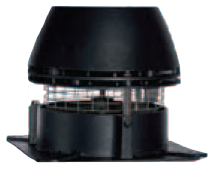
The use of mechanical extract fans in flues may be used to overcome the design issues like flue diameter and flue routes.
The appliance should be controlled by a combustion flow switch which will safely shut down the appliance in case of draught failure.
The fan should be sized according to the proposed installation with specific information about the appliance, the flue size, the flue route and the termination point crucial to the specification of the fan.
Twinning Boilers
The twinning of boilers into one flue should only be designed and installed by a competent chimney specialist in accordance with BSEN 13384-2:2003+A1:2009. The installation must be notified to the Local Authority Building Control Officer for approval.
A bio-mass appliance should never be incorporated into a gas/oil fired flue system.
Concentric Chimneys
Concentric chimneys can overcome the problems with down draught and percussive events. Cowls tend not to be effective on chimneys with a flue diameter below 150mm. The use of a concentric flue is specific to the appliance, so manufacturer’s guidance must always be sought.
The positioning of the air in and out vents is important. They must not be too close. Concentric chimneys can only be used when the chimney height is between 4.5 & 17m.
Uninsulated systems should only be used internally. Building Control must approve a concentric chimney as an alternative installation method.
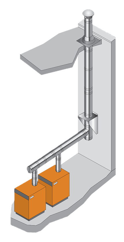 Typical condensing boiler cascade system with single wall connecting flue pipe and twin wall
The function of a flue or chimney is to discharge the products of combustion. The purpose of the Clean Air Act and the Environmental Protection Act is to regulate how these gases can be dispersed safely in the atmosphere. The Clean Air Act Memorandum is used to calculate the required height of a chimney or flue.
Chimney height is one of the main chimney/flue features used, by local authorities, to control the discharge of emissions into the atmosphere. The required discharge height is calculated to render emissions harmless and not prejudicial to public health. The calculations used to determine the chimney height take into account the type of fuel burned and the maximum rated output of the appliance.
The discharge velocity of the emissions from a chimney is another important factor in determining how readily emissions are dispersed. The higher the discharge velocity the better the dispersion rate. It is essential to prevent the exhaust gases flowing down the outside of the chimney or flue.
When designing the chimney/flue system it is important to design the chimney/flue so that the required discharge velocity can be achieved. With boiler systems it is often necessary to reduce the internal diameter of the chimney top by using a tapered cone. Care should, however, be taken to calculate the correct size of tapered cone.
The maintenance of a constant discharge velocity can be difficult when more than one appliance is serviced by one chimney. In this situation an exhaust fan may be required. Adjacent buildings can also have an impact on the required chimney or flue height and must be taken into consideration when calculating the chimney/flue height.
It should always be borne in mind that the objective is to achieve an effective and safe chimney discharge height, rather than a minimum discharge height.

The BFCMA recommends following a 10 point check list. Start with matching the appliance and the flue. (Attention should be paid to the appliance manufacturer’s recommendations. If in doubt contact the chimney manufacturer or distributor). Then look at the chimney height and emissions.
1 Determine the necessary height to create the optimal draught to meet appliance operating requirements. Approved Document J provides clear guidance.
2 Factor in site-specific environmental impacts on the chimney draught. The local terrain (proximity of trees and higher buildings, for example) will have an impact on the performance of the chimney.
3 The heat output of the appliance and the total kW/hr rating of the boiler room need to considered, along with the appliance efficiency.
4 The type of fuel to be used will have an impact on emissions.
5 DEFRA Smoke Control Areas require the installation of an exempted appliance. This, however, only covers the appliance. The correct chimney height has still to be calculated.
6 Building regulations requirements must always be referenced.
7 The requirements of BSEN15287-2:2008 should be followed for appliances with a kilowatt rating above 50kW.
8 When considering the requirements of the Clean Air Act for wood burning appliances with a burn rate above 45.4 kg/hr the Biomass Assessment Tool (TG09) should be used. This tool takes into account the post code of the installation.
9 A location is designated a LQMA area if the air quality breaches the required limits. In a LQMA area it is the local authority’s responsibility to measure and approve the installation of the appliance.
10 Finally Dispersion Modelling may be required for larger appliances. No one point will, on its own, determine the final required height. Usually more than one will have an actual impact and affect the final determined termination height of the chimney. In a nutshell the process begins and ends with flue sizing. The applicability of some points are dependent on the kW rating of the appliance and the boiler room.

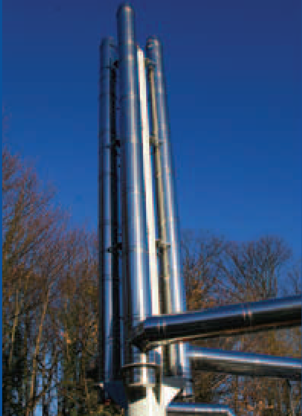
 Typical biomass installation from top outlet using twin wall system chimney.
Low Level Discharge from Horizontal Flues
There is a suggestion that the use of low level discharge from horizontal flues should be extended to cover Type C appliances with a net heat input between 70kW and 333kW. The BFCMA does not support this suggestion on the grounds laid out in the previous section ‘Chimney or Flue Height and the Clean Air Act’. As discussed chimney/flue height has a significant impact on the dispersion of emissions.
The risk assessment suggested by IGEM before such a low level discharge be undertaken would rule out its use in virtually all situations. The use of low level discharge should not be carried out if the flue termination is within a light well or close to a road, property boundary or an area which is used for general public access. This would include an area used for car parking.
Furthermore, the proposed flue termination must not be directly adjacent to a playground, school yard, seating area or any area that can be used for a public gathering. The proposed flue termination must not be enclosed on more than two sides by walls or solid structures which project higher than the chimney/ flue termination. The proposed installation should not cause a nuisance to adjoining properties and should not allow the build-up of emissions under unfavourable atmospheric conditions. (See IGEM Guide UP/Edition 4 Communication 1774 ‘Installation of flued gas appliances in industrial and commercial appliances’).
The appliance manufacturer’s instructions on inspection and cleaning should be followed. The flue should be maintained and cleaned on a regular basis. It is important to sweep the chimney on a regular basis to remove soot and tar.
It is also good practise to check at least every year or two the exposed parts of a chimney, flashings and terminals for signs of damage.
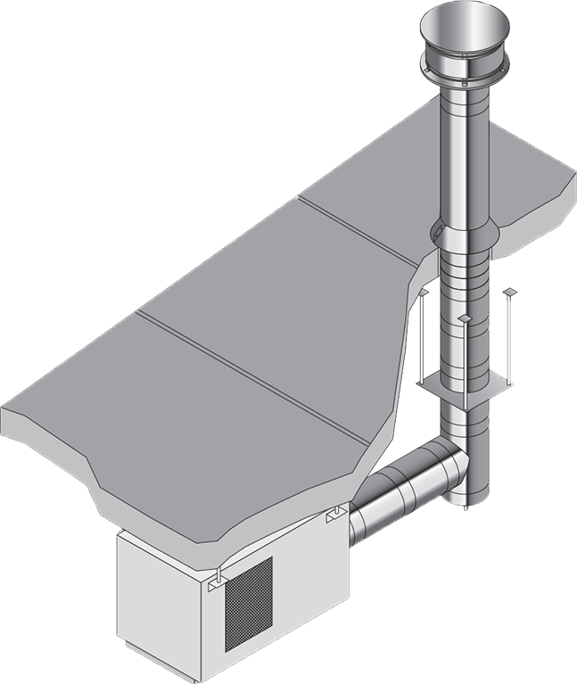 Typical system chimney on industrial space heater
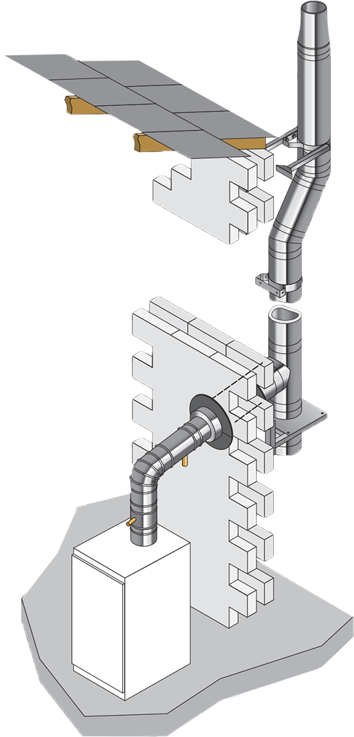 Typical condensing flue pipe on condensing boiler
The drawings and photographs are courtesy of Exodraft, Poujoulat (UK) and Schiedel Rite Vent. The 10 point check list for chimney height is courtesy of Poujoulat (UK). The drawings in this guide are for illustration purposes only and do not necessarily represent an actual intallation. Manufacturer’s installation instructions should always be consulted before installation.

